18. Magnetic Forces
18.1. Lorentz Force
We discussed in Equation (14.2) the definition of electric fields based on the Coulombic force, giving us the relation between the force \(\bf F\) acting on a charge \(q\) sitting in an electric field \(\bf E\):
A natural question now is what is the analogous expression for charges in a magnetic field \(\bf B\)?
To find an answer to this, lets think about current flowing in a wire and the resulting magnetic field:
There is a force acting on the charges (due to a potential difference), which pushes the charges in the cylindrical \(\hat{\bf z}\) direction, this produces a perpendicular (radial) magnetic field \(\bf B(r)\), which by the Biot-Savart law is in the \(\hat{\theta}\) direction. Therefore it should not come as a great surprise that the effect on a charge \(q\) moving with velocity \({\bf v}\) in a magnetic field \({\bf B}\) is a force that also acts in a perpendicular direction to both the field and the velocity \(F \propto {\bf v} \times {\bf B}\), thus the magnetic force follows:
We can write the total force acting on a charge \(Q\) moving with a velocity \({\bf v}\) in an electric field \({\bf E}\) and a magnetic field \({\bf B}\):
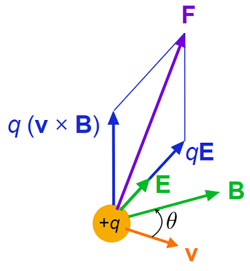
Fig. 18.1 A graphical depiction of the Lorentz force on a point charge \(+q\), the \(\bf E,\, B\) fields are depicted, alongisde the momentary velocity \(\bf v\) and each of the individual components of the force and the overall force.
This is know as the Lorentz force and shows a few differences between the electric \({\bf E}\) and magnetic \({\bf B}\) fields acting on a charge \(q\):
The force \({\bf F}_E\) due to the electric field acting on \(q\) is simply proportional and in the same direction of the the field \({\bf E}\).
The force \({\bf F}_B\) due to the magnetic field acting on \(q\) is proportional to the magnitude of the magnetic field and charge velocity, but moves in a perpendicular direction to both, due to the cross product \({\bf v}\times{\bf B}\).
The magnetic force \(|{\bf F}_B| = q|{\bf v}||{\bf B}|\sin(\theta)\), which means that if \(|{\bf v}| = 0\), there is no charge due to the magnetic field. Therefore we see that if there is no charge velocity, the magnetic field has no effect on charges, it is only because moving charges produce a magnetic field that an external field may then interact with it. Additionally this means if the magnetic field \({\bf B}\) is directed parallel to the charge velocity \({\bf v}\) i.e. \(\theta = 0\), then the magnetic field has no effect on charges. Likewise we see a maximum force felt with \(\theta = \pi/2\), i.e. perpendicular charge velocity to magnetic field.
18.2. Laplace Force
If we put a wire carrying a current \(I\), which has electrons moving with a drift velocity \(v\), in a magnetic field \(\bf B\), then by Ampère’s law the currents magnetic field \(\bf B\) should interact, producing some reaction force \(\bf F\) on the wire. From Equation (17.3), we find:
therefore using the Lorentz force law, the force on a wire of length \(L = |\bf L|\) within a magnetic field \(\bf B\) will follow:
which we depict in Fig. 18.2, showing a straight wire meeting a uniform magnetic field at an angle \(\alpha\). This is sometimes known under the name of the Laplace Force or colloquially as F is BIL.
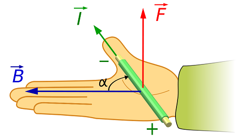
Fig. 18.2 Right-hand rule for the force \(\bf F\) on a wire carrying a current \(I\) in a uniform magnetic field \(\bf B\), with the wire meeting the field at an \(\alpha\) (the vector \(L\) is aligned with the direction of conventional current).
Likewise if we wish to calculate the force on wire that is not straight, we can use the expression from Equation (18.2):
where we consider the line segments \(\mathrm{\bf d} \ell\) over the length of the wire and then integrate up.
18.3. Ampère’s Force Law*
Given current carrying wires can produce magnetic fields, neighbouring current carrying wires can therefore feel mutual magnetic fields. We find that this combination of currents and fields causes a force, as depicted in Fig. 18.3.
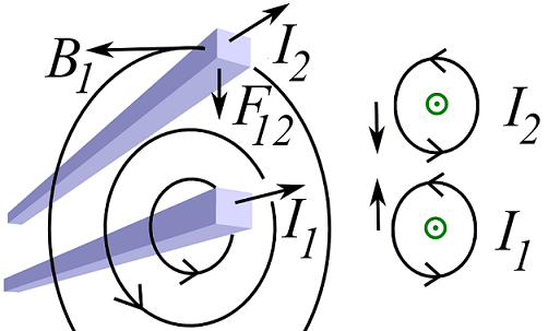
Fig. 18.3 Depiction of magnetic forces,
Left Pane - parallel wires magnetic fields and force \(F_{12}\) - there will also be an equal and opposite \(F_{21}\) due to the field from \(I_2\)
that we have not depicted here.
Right Pane - face on magnetic fields of each wire, showing opposing magnetic field directions and hence a mutual attractive force.
The neighbouring wires magnetic fields are in opposite directions and therefore the force is attractive. We can motivate the form of the force on wire 2 \(F_{12}\), due to wire 1’s current \(I_1\) by thinking about the effect of currents and magnetic fields: Using this expression for the forces on charges, we find that a current element in wire 2, \(I_2\,\mathrm{\bf d} \ell_2 = \mathrm{d} Q_1 \,{\bf v}_1\) would feel a force due to a moving charge element in wire 1, \(I_1\,\mathrm{\bf d} \ell_1\) producing a magnetic field, according to:
For the case of an infinite parallel current carrying wires, separated by a distance \(d\), the force on wire 2 due to current in wire 1 is given by:
where as we see the force is attractive between the two wires carrying currents in the same direction. Obviously is the currents are reversed then a repulsive force would be detected between the wires. If the wires are not parallel, then the cross products in Equation (18.3) would take care of the necessary resolving of components.